


2. Institute of Chemical Materials, China Academy of Engineering Physics, Mianyang 621999, China;
3. China Academy of Engineering Physics, Mianyang, 621999, China
2. 中国工程物理研究院化工材料研究所,四川 绵阳 621999;
3. 中国工程物理研究院,四川 绵阳 621999
In the 1970s, J. R. Stroud invented the slapper detonator based on the characteristic of electrical explosion of a metal bridge foil under a large pulse current and the mechanism of short-pulse shock-initiation of explosive[1-2]. Energy conversion unit, which could convert the electrical energy of bridge foil into kinetic energy of flyer, was the core component of slapper detonator. In general, energy conversion unit was mainly composed of reflector, bridge foil, flyer and barrel. When a large pulse current passed through bridge foil, rapidly expanding plasma generated from an explosion of a metal foil drove a flyer stuck on the bridge foil across the barrel, and its high-velocity impact on the explosive then delivers the energy and shock needed to initiate a detonation, which could achieve energy output.
Since the slapper detonator was invented, the development of fabrication process of energy conversion unit could be divided to three phases: (1) the first-generation energy conversion unit based on traditional machining technology and precision assem bly technology[3-5]; (2) the second-generation energy conversion unit based on integrated design and fabrication of circuit technology[6-10]; (3) the third-generation energy conversion unit based on MEMS technology[11-14]. Compared to the traditional machining technology, the integrated circuit technology and MEMS technology were beneficial to the integrated and batch manufacturing of the energy conversion unit. So, the gap between bridge foil and flyer as well as the gap between flyer and barrel could be strictly controlled. This could prevent extra energy loss generated due to these gaps during the process of electrical explosion of metal foil, reducing the driving flyer capability and leading to non-detonation of explosive or misfire of slapper detonator.
In this paper, we utilize Flexible Printing Circuit, also called FPC or soft board, to design a structure of energy conversion unit. Compared with the traditional method, we adopted a new substrate and barrel material, and the new manufacturing method can ensure the consistency of product manufacturing process and action process. Utilizing the Voltage and current test methods, Photonic Doppler Velocimetry method and D-optimal method, we studied the electrical explosion performance, driving flyer capability and initiating HNS-Ⅳ explosive capability of the integrated energy conversion unit.
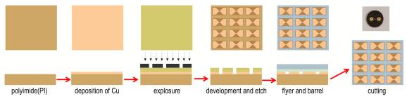
2 Experiment 2.1 Fabrication ProcessWe designed and fabricated the energy conversion unit based on FPC process. In the fabrication process, the material of substrate, flyer and barrel was polyimide (PI), and that of bridge foil was copper. The whole processes could be automated in the production line of FPC, as shown in Fig. 1. Firstly, the PI film was cut into several 6 cm square substrates, and then a 6-μ m copper film was sputtered on the PI substrate by magnetron sputtering method. After that, the copper film was etched into the shape of a bridge foil by chemical etching means, wherein the size of the bridge region is 0.5 mm×0.5 mm. The flyer layer was attached to the surface of the copper foil, and then the barrel layer was attached to the surface of the flyer layer. The diameter of the barrel was 0.5 mm and its thickness was also 0.5 mm. Finally, the transducer was cut into single units by clipping.

|
Fig.1 Fabrication process diagrams of integrated energy conversion unit |
A capacitor discharge unit was utilized to study electrical explosion performance of energy conversion unit, as shown in Fig. 2. The capacitance value was 0.22 μF, and high-voltage switch was three-dimensional trigger tube. In the experiment, high-voltage probe was utilized to measure the voltage change of bridge foil, and Rogowski coil was utilized to measure the current change of discharge circuit, which were all recorded in an oscilloscope. To characterize driving flyer capability of energy conversion unit, Photonic Doppler Velocimetry(PDV) was utilized to measure the velocity history of flyer. D-optimal method was used to evaluate the ability of the transformer initiating HNS-Ⅳ explosive.

|
Fig.2 Schematic diagram of the capacitor discharge unit |
Figure 3 represented the voltage and current change of bridge foil in the discharge circuit unit with the capacitor voltage of 2700 V. As can be seen from Fig. 3, current cycle time of discharge circuit is 1212 ns, and the peak value of current is 2300 A. Burst time of bridge foil could be determined by voltage curve of bridge foil. As usual, we consider burst time of bridge foil as the peak time of voltage measured from energy conversion unit. From Fig. 3, the value of burst current is 2200 A, and corresponding to the burst time is 216 ns.

|
Fig.3 Voltage and current curves of the discharge circuit at capacitor voltage value of 2700 V |
Figure 4 represented cycle time of discharge circuit, current peak value, burst current, burst voltage and burst time under different voltage value of capacitor. As can be seen from Fig. 4, the discharge time is stable around the value of 1200 ns, indicating that structure and composition of discharge circuit under different charging voltage are stable. The peak value of current of discharge circuit linearly increases with increasing of capacitor voltage, and burst current change is rendered as similar law from 2080 A to 2680 A. However, burst time of bridge foil linearly decreased from 232 ns to 156 ns with capacitor voltage increasing. Increase of burst current and decrease of burst time of bridge foil were in favor of accelerating energy deposition during the process of electrical explosion of bridge foil, which might achieve higher flyer velocity. Results indicate that characteristic of energy conversion unit based on FPC fabrication process has similar law as that based on traditional machining process reported in literature[15]. Material type of tamper and barrel hardly influenced mechanism and characteristics of energy conversion unit.

|
Fig.4 Influence of capacitor voltage on burst parameters of bridge foil |
Flyer driving capability of energy conversion unit was an important performance of characterizing energy conversion efficiency. Photonic Doppler Velocimetry (PDV) was utilized to measure flyer velocity history generated by integrated and traditional manual assembly energy conversion unit under different charging capacitor voltage. As shown in Fig. 5, we prepared the test samples using the traditional manual assembly method and the integrated manufacturing method. And we test 5 times under each charging capacitor voltage.

|
Fig.5 Diagrams of two types of flyer velocity measurement samples |
Figure 6 represented the typical flyer velocity curve. From Fig. 6, the peak value of flyer velocity could be obtained. Mean and standard deviation of flyer maximum velocity of each five tests could be calculated and analyzed, and the results were shown in Fig. 7. From Fig. 7, with capacitor charging voltage increasing, mean value of flyer velocity generated by integrated energy conversion unit continuously increased from 4056 m·s-1 to 4589 m·s-1, and standard deviation value of that were stable between 38 and 48, which was compared with mean value of flyer velocity generated by manual assembly energy conversion unit increasing from 4150 m·s-1 to 4320 m·s-1 and standard deviation value of that varying between 109 and 220. It is obvious that standard deviation generated by manual assembly energy conversion unit greatly exceed that of integrated energy conversion unit. This′s due to axial compression depending on the traditional manual assembly sample may lead to gaps among bridge foil, flyer and barrel. Meanwhile, these gaps can increase energy dissipation and decrease driving flyer energy. Besides, because manual assembly can bring uncertainty, standard deviation of flyer velocity may increase. From the experiment results, integrated energy conversion unit has significant advantages in terms of energy efficiency and action consistency in the flyer driving process.

|
Fig.6 Experimental results of flyer velocity at peak current of 2300 A |

|
Fig.7 Experimental results of flyer velocity for five times test |
Slapper detonator was composed of energy conversion unit, HNS-Ⅳ pellet, connectors and shell. Detonation sensitivity tests were carried out according to D-optimal method. In the tests, the discharge capacitance value of test device was 0.22 μF. The firing current with probability value of 50% and 99.9% of detonating HNS-Ⅳ explosive were respectively calculated at a confidence level of 0.95 as shown in Table 1. At a confidence level of 0.95, firing current of the integrated energy conversion sample with 50% probability of detonating HNS-Ⅳ explosive never exceeds 1.89 kA, while that with 99.9% probability of detonating HNS-Ⅳ explosive does not exceed 2.1 kA. Under the same experimental condition, the firing current of energy conversion unit based on traditional manual assembly with 50% probability of detonating HNS-Ⅳ explosive never exceed 2.07 kA, while that with 99.9% probability of detonating HNS-Ⅳ explosive does not exceed 2.34 kA. It′s obvious that the detonation threshold of the integrated energy conversion unit is lower, which further indicates that the energy conversion unit based on FPC process has significant advantages in terms of energy efficiency and action consistency.
| Table1 Experimental results for initiating HNS-Ⅳ explosive |
An integrated energy conversion unit component based on FPC process, utilizing capacitor discharge circuit, was designed and fabricated. Meanwhile, performances of energy conversion unit, such as electrical explosion performance, driving flyer capability and initiating HNS-Ⅳ capability, were characterized. Research indicates that electrical explosion performance of energy conversion unit fabricated by FPC process has a similar law as that fabricated by traditional manufacturing process, while integrated structural design and automated production process make significant progress in driving flyer capability. Detonation sensitivity tests of HNS-Ⅳ explosive were carried out according to D-optimal method. Results indicate that at a confidence level of 0.95 firing current of the integrated energy conversion unit with 99.9% probability of detonating HNS-Ⅳ explosive never exceeds 2.1 kA, which is lower than that of energy conversion unit fabricated by traditional manufacturing process (2.340 kA).
| [1] |
Stroud J R, Ornellas D L. Flying plate detonator using a high-density high explosive: United States Patent, 47988913 [P]. 1978.
|
| [2] |
Stroud J R. A new kind of detonator-the slapper[R]. UCRL 77639: 1976.
|
| [3] |
Jeffrey A L. Exploding Foil Initiator Qualifications [R]. RD-ST-91-16: 1993.
|
| [4] |
Martinez E C. Bidirectional Slapper Detonators in Spherical Explosion System[R]. LA-11816: 1984.
|
| [5] |
McCormick R N, Boyd M D. Bidirectional Slapper Detonator: United States Patent, 4471697[P]. Sep. 18, 1984.
|
| [6] |
Williams M R, Werling S V. Slapper Detonator: United States Patent, 5370053[P]. Dec. 6, 1994.
|
| [7] |
O′Brien D W, Druce R L, Johnson G W, et al. Method and System for Making Integrated Solid-state Fire-sets and Detonator. United States Patent, 5731538[P]. Mar. 24, 1998.
|
| [8] |
Bower S, Coaker B M. Recent developments in exploding foil initiator (EFI)based electronic safety, arming and initiation systems. http://www.e2v.com,accessed 30 January2016.
|
| [9] |
e2v aerospace & defense inc. e2v complex weapon safety, arming and initiation. http://www.e2v-us.com, accessed 25 July2017.
|
| [10] |
Zhu P, Chen K, Xu C, et al. Development of a monolithic micro chip exploding foil initiator based on low temperature co-fired ceramic[J]. Sensors and Actuators A: Physical, 2018, 276: 278-283. DOI:10.1016/j.sna.2018.04.032 |
| [11] |
Garvick D R, Fan L C, Kuester B R, et al. MEMS Energetic Actuator With Integrated Safety and Arming System for A Slapper Detonator. United States Patent, 61733650[P]. Jan. 16, 2001.
|
| [12] |
Schmidt M. Chip slapper detonator processing for rapid prototyping and hydrodynamic properties[R], Lawrence Livermore National Laboratoy, CA, USA, 2007.
|
| [13] |
Cope R D. NAVAIR Fuze Overview[C]//NDIA 48th Annual Fuze Conference, Charlotte, NC, 2004.
|
| [14] |
Xu C, Zhu P, Chen K, et al. A highly integrated conjoined single shot switch and exploding foil initiator chip based on MEMS technology[J]. IEEE Electron Device Letters, 2017, 38(11): 1610-1613. DOI:10.1109/LED.2017.2752749 |
| [15] |
Chen Q C, Fu Q B, Chen L, et al. Parametric influences of the sensitivity of explding foil initiators[J]. Propellants, Explosive, Pyrotechnics, 2014, 39(4): 558-562. DOI:10.1002/prep.201300108 |
Exploding foil energy conversion unit based on Flexible Printing Circuit process was designed and fabricated. Meanwhile, electrical explosion performance, driving flyer capability and initiating HNS-Ⅳ capability of the new integrated exploding foil energy conversion unit were studied.