


2. School of Chemical Engineering, Anhui University of Science and Technology, Huainan 232001, China;
3. Department of Modern Mechanics, University of Science and Technology of China, Hefei 230027, China
2. 安徽理工大学化学工程学院, 安徽 淮南 232001;
3. 中国科学技术大学近代力学系, 安徽 合肥 230027
The equipment in industrial field has been working under bad environment such as high temperature, electromagnetic radiation, heavy erosion, overload. To ensure working steadiness for a long time, the equipment in industrial field put forward higher requirements for the performance of the material. The explosive welding technique makes flyer plate produce plastic deformation, motion, collision with base plate, melting and interatomic combination with base plate through high energy which is released by the explosives[1]. Explosive welding, which has the advantages of simple process, low cost, good performance and abundant energy sources, has become a very important connection method in metal processing.
The macroscopic physical phenomena of crackingat the initiation end and terminal of composite plates called boundary effect often appear in explosive welding production. Many experiment studies were carried out on the boundary effect of explosive welding. Li et al[2] reported that the real stand off distance at the edge area was much larger than that at the internal area. As the stand off distance increasing, the acceleration time of edge area increases so that the collision energy becomes larger, which lead to the boundary effect. Zheng et al[3] considered that the inertia force repeatedly act on the edge area of metal materials when the detonation wave propagate to the edge of materials. In such case, the energy is too high at the edge area of metal materials so that the boundary effect can be found in explosive welding. Liu et al[4] showed that the internal cause of boundary effect is softening of flyer plate materials and the external cause is tension stress wave at the edge area of composite plates.
Due to the properties of complexity, instantaneity and high pressure of explosive welding process, the experiment research on explosive welding is very difficult. It is distinctly meaningful to investigate the explosive welding through numerical simulation. Lazari et al[5] and Al-Hassani et al[6] investigated the transient response of metal plates under explosive loading by the finite element. Oberg et al[7] used a Lagrangian finite difference computer code to simulate explosive welding, but only produced jetting. Akbari et al[8] successfully produced wave interfaces and jet phenomena in explosive welding by numerical simulation. Wang et al[9] reproduced the interfacial waves and jetting in explosive welding by SPH method. The historical changing processes of effective plastic strain, shear stress were clearly shown in the simulations, which helpful to understanding the requirements of the wave formation.
The boundary effect seriously affects the product quality, so further discussion on boundary effect has important value in explosive welding. At present, there are few reports about the numerical simulation of boundary effect at home and abroad. In this paper, the Smoothed Particle Hydrodynamics (SPH) method, which is the one of method of gridless Lagrangian hydrodynamics using particles, was applied to study the generation mechanism of boundary effect. According to the generation mechanism, the preventive measures were proposed to against the boundary effect.
2 Methodology 2.1 SPH MethodThe SPH method[10] is based on a gridless Lagrangian hydrodynamics using particles. That is to say, a set of moving interpolation points which follow the fluid motion is defined instead of relying on the use of a computational mesh. The most attractive feature of SPH method is that it gets rid of the computation termination due to the possible large element distortion inherent in other Lagrangian formulation based on finite element methods. SPH method was originally developed for astrophysics and shock simulation. But now, Its applications include hypervelocity impact, detonation and super-fast large deformation problems[9, 11-14]. The special feature of the SPH method is very attractive for solving the problem concerning the large deformation.
In SPH method, the fluid is represented by a finite set of observation points or particles, through the use of a smoothing procedure in which the value
| $\hat f\left( x \right) = \int_{ - 2h}^{2h} {f\left( {x'} \right)W\left( {x - x',\;h} \right){\rm{d}}x'} $ | (1) |
Where W(x-x′, h) is a smooth function, commonly referred to as the interpolating kernel, and h is the smooth length corresponding to the mesh size in finite element method(FEM) analysis. x and x′ are location of the point of mass I and particles J within the smooth length h from particle I respectively. Kernel function W must satisfy the follow conditions:
| $\int_{ - 2h}^{2h} {W\left( {x - x',\;h} \right){\rm{d}}x' = 1} $ | (2) |
| ${\lim _{h \to 0}}W\left( {x - x',\;h} \right) = \delta \left( {x - x'} \right)$ | (3) |
| $W\left( {x - x',\;h} \right){\rm{d}}x' = 0$ | (4) |
When |x-x′| > κh. κ is a constant that related to smooth function of x point.
Derivatives of
| $\nabla \hat f\left( x \right) = \int_{ - 2h}^{2h} {f\left( {x'} \right)\nabla W\left( {x - x',\;h} \right){\rm{d}}x'} $ | (5) |
Numerical modeling of the explosive welding was developed with the dynamics modeling software LS-DYNA, incorporated with the SPH method. To save the computer resources and reduce the calculation time, the analysis of the object was carried out on SPH-2D models, as shown in Fig. 1. Thickness and length of flyer plate, base plate and explosives are 2 mm and 30 mm, 16 mm and 30 mm, 10 mm and 30 mm respectively. The stand off distance is 4 mm. The particle size plays an important role in visualizing the jetting particles and interface profiles. The thickness of the jetting is about 2%~4% of the thickness of flyer plate in the explosive welding process[15]. In order to reproduce the jet, the particle size Δr used in this study is 25 μm. All units adopted in the model are μs for time, cm for length and g for weight.

|
Fig.1 The calculation model |
At present, Johnson-Cook model[16] is commonly used to describe the behavior of deformable materials. Jones-Wilkins-Lee(JWL) state equation[17] is for the explosives.
Johnson-Cook Model, considering deforming rate and temperature together to describe the mechanical behavior of metals under high-speed collision driven by explosive detonation as well as strain-rate hardening and temperature softening, is written as:
| $\sigma = \left( {A + B\varepsilon _p^n} \right)\left[ {1 + C\ln \;\dot \varepsilon _p^*} \right]\left( {1 - {T^{*\;m}}} \right)$ | (6) |
in which A, B, C, n and m are Johnson-Cook material constants, T*=(T-Tr)/(Tm-Tr) where Tr (K) is the room temperature and Tm (K) is the melting temperature of material, εp is the effective plastic strain,
Both flyer plate and base plate are assigned material property of Q235 steel, the parameters used in Johnson-Cook model are listed in Table 1.
| Tab.1 Johnson-Cook parameters of Q235 steel[18] |
Jones-Wilkins-Lee (JWL) state equation, the governing equation, is utilized for describing the relation between pressure and volumetric strain of explosive, expressed as:
| $p = A\left( {1 - \frac{\omega }{{{R_1}\;V}}} \right){e^{ - {R_1}\;V}} + B\left( {1 - \frac{\omega }{{{R_2}\;V}}} \right){e^{ - {R_2}\;V}} + \frac{{\omega {E_0}}}{V}$ | (7) |
where A, B, R1, R2 and ω are all material constants, p(GPa), V and E0 (kJ·cm-3) are the pressure, relative volume and initial internal energy, respectively.
Emulsion explosives (The mass fraction of hollow glassmicroballoons is 5%) is adopted here, whose parameters in JWL equation of state (EOS) are listed in Table 2.
| Tab.2 JWL EOS parameters of emulsion explosives[19] |
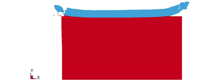
The flight attitudes of flyer plate at different times are shown in Fig. 2.

|
Fig.2 The flight attitudes of flyer plate at different time |
As shown in Fig. 2d, jetting was reproduced in the graphical output from the simulation. As shown in Fig. 2, the flight attitude of flyer plate produced a negative collision angle is in agreement with the flight attitude of flyer plate concluded from experiment and calculation results in the reference [20].
3.2 DiscussionCombined with Fig. 2a-Fig. 2b, schematic representation of the flight attitude of flyer plate at the initiation end can be obtained as shown in Fig. 3.

|
Fig.3 Schematic of the flight attitude of flyer plate at the initiation end |
It can be found in Fig. 3 that the collision angle of flyer plate at the initiation end is negative. The reason for this phenomenon is that the detonation products at the initiation end of explosives is affected by rarefaction wave. In this case, the pressure of detonation products decays rapidly at the initiation end. In other words, the velocity of flyer plate at the initiation end is much lower than that close to the centre. Then a negative collision angle is produced. Produced by detonation products of explosives, the force F at the initiation end of flyer plate can be divided into two parts: F1 and F2. F1 is the force which makes the flyer plate down, namely bonding force. F2 is the force which can generate the boundary effect. F2 can be expressed as: F2=Fsinθ. It shows that the initiation end of flyer plate can be torn at a certain angle.
Combined with Fig. 2c-Fig. 2d, schematic representation of the flight attitude of flyer plate at the terminal can be obtained as shown in Fig. 4.

|
Fig.4 Schematic of the flight attitude of flyer plate at the terminal |
As shown in Fig. 4, β is the collision angle of flyer plate at the terminal and β1 is the collision angle of flyer plate close to the centre. It can be found that β is larger than β1. The reason for this phenomenon is that the detonation products at the terminal of explosives is affected by rarefaction wave. In this case, the pressure of detonation products decays rapidly at the terminal. In other words, the velocity of flyer plate at the terminal is much lower than that close to the centre. Then the collision angle at the terminal is larger than that close to the centre. Produced by detonation products of explosives, the force F′ acting on the terminal of the flyer plate can be divided into two parts: F3 and F4. F3 is the downward collision force, namely bonding force. F4 is the force which can generate the boundary effect. The magnitude of this force can be expressed as: F4=F′sinβ. A jet is the necessary condition for explosive cladding. The production condition of jet is 5° < β < 25°. At this angle range, F4 is 8.72%-42.26% of the F′. The collision angle of terminal is larger than the centre. It shows that the terminal of flyer plate can be torn at a certain angle.
As can be seen from Fig. 2, the flyer plate fracture occurs before collision happened. namely, the flyer plate fracture has occurred during acceleration. It can be obtained that the cause of boundary effect is not due to excess energy at the edge area. With the effect of rarefaction wave at the boundary of detonation products, the velocity difference is existed at the boundary and internal of composite plate, so that the collision angle at the boundary of composite plate is bigger than the internal of composite plate. The pressure of detonation products can tear the initiation end and terminal of composite plates.
In order to eliminate the effect of boundary effect in explosive cladding, the way of increasing the area of charge and flyer plate is widely adopted at present[2-3]. Although this method is very effective, it can lead to increased costs. In our prophase research [21], honeycomb structure explosives and double sided explosive are used to resolve the low energy efficiency of explosives. Fig. 5 is the sample of composite plate produced by honeycomb structure explosives and double sided explosive cladding. It can be found that boundary effect does not appear at the edge area of composite plates. Due to multi-directional constraint of honeycomb material and double sided flyer plates, the effect of rarefaction wave effectively reduces. Using honeycomb structure explosives and double sided explosive cladding, the boundary effect can be effectively controlled without increasing the charge size and flyer plate size. The effective bonding area is much higher. It will not only save costs but also beneficial to environmental friendly.

|
Fig.5 Composite plates produced by honeycomb structure explosives and double sided explosive cladding |
(1) The simulation results reproduce the phenomenon of jetting, showing that SPH method is effective for explosive cladding.
(2) The cause of boundary effect is not due to excess energy at the edge area. With the effect of rarefaction wave at the boundary of detonation products, the velocity difference is existed at the boundary and internal of composite plate, so that the collision angle at the boundary of composite plate is bigger than the internal of composite plate. The pressure of detonation products can tear the initiation end and terminal of composite plates.
(3) Due to multi-directional constraint of honeycomb material and double sided flyer plates, the effect of rarefaction wave is effectively reduced. Using honeycomb structure explosives and double sided explosive cladding, the boundary effect can be effectively controlled without increasing the charge size and flyer plate size. The effective bonding area is much higher. It will not only save costs but also beneficial to environmental friendly.
| [1] | Crossland B, Williams J D. Explosive welding[J]. Metals Review, 1970, 15(1): 79-100. DOI:10.1179/imr.1970.15.1.79 |
| [2] | Li X M, Jiao Y G. Generation and elimination of boundary effect of explosive welding for thick plate of TA10 alloy and steel[J]. Rare Metals Letters, 1999, 10: 5-6. |
| [3] | Zheng Y M. Explosive welding and metallic composite and the engineering application[M]. Changsha: Central South University Press, 2007. |
| [4] | Liu P, Lu M, Ji X W, Pang J J. Reasons of end-cracking of explosively welded TA2/Q235 steel composite plates[J]. Materials for Mechanical Engineering, 2012, 36(1): 48-51. |
| [5] | Lazari G L, Al-Hassani S T S. Solid mechanics approach explosive welding composite[C]//Proceedings 8th International Conference on High Energy Rate Fabrication, San Antonio, 1984. |
| [6] | Al-Hassani S T S, Salem S A, Lazari G L. Explosive welding of flat plates in free flight[J]. International Journal of Impact Engineering, 1984, 1(2): 85-101. |
| [7] | Oberg A, Schweitz J, Olfsson H. Computer modelling of the explosive welding process[C]//Proceedings of the International Conference on High Energy Rate Fabrication, San Antonio, Texas, 1984. |
| [8] | Akbari Mousavi A A, Al-Hassani S T S. Numerical and experimental studies of the mechanism of the wavy interface formations in explosive/impact welding[J]. Journal of the Mechanics and Physics of Solids, 2005, 53(11): 2501-2528. DOI:10.1016/j.jmps.2005.06.001 |
| [9] | Wang X, Zheng Y Y, Liu H X, et al. Numerical study of the mechanism of explosive/impact welding using Smoothed Particle Hydrodynamics method[J]. Materials and Design, 2012, 35: 210-219. DOI:10.1016/j.matdes.2011.09.047 |
| [10] | Kong X S, Wu W G, Li J, et al. A numerical investigation on explosive fragmentation of metal casing using Smoothed Particle Hydrodynamic method[J]. Materials and Design, 2013, 51: 729-741. DOI:10.1016/j.matdes.2013.04.041 |
| [11] | Hayhurst C J, Clegg R A. Cylindrically symmetric SPH simulations of hypervelocity impacts on thin plates[J]. International Journal of Impact Engineering, 1997, 20(1-5): 337-348. DOI:10.1016/S0734-743X(97)87505-7 |
| [12] | Wang W, Huang Y, Grujicic M, et al. Study of impact-induced mechanical effects in cell direct writing using smooth particle hydrodynamic method[J]. Journal of Manufacturing Science and Engineering, 2008, 130(2): 0210121-02101210. |
| [13] | Varas D, Zaera R, López-Puente J. Numerical modelling of the hydrodynamic ram phenomenon[J]. International Journal of Impact Engineering, 2009, 36(3): 363-374. DOI:10.1016/j.ijimpeng.2008.07.020 |
| [14] | Sauer M. Simulation of high velocity impact in fluid-filled containers using finite elements with adaptive coupling to smoothed particle hydrodynamics[J]. International Journal of Impact Engineering, 2011, 38(6): 511-520. DOI:10.1016/j.ijimpeng.2010.10.023 |
| [15] | Shao B H, Zhang K. Explosive welding principle and its application[M]. Dalian: Dalian University of Science and Technology Press, 1987. |
| [16] | Cheng G Q, Li S X. A thermo-viscoplastic constitutive model of metallic materials at high strain rates[J]. Journal of Ballistics, 2004, 16(4): 18-22. |
| [17] | Li Y C, Shi D Y, Zhao Y. The basic theory and engineering practice of ANSYS11.0/LS-DYNA[M]. Beijing: China Water and Power Press, 2008. |
| [18] | Shi D Y, Li Y C, Zhang S M. Dynamic analysis based on ANSYS/LS-DYNA8.1[M]. Beijing: Tsinghua University Press, 2005. |
| [19] | Song J Q. Research on detonation characteristics of emulsion explosives[D]. Beijing: University of Science and Technology Beijing, 2000. |
| [20] | Rao C Q. The explosive welding of thick stainless steel and carbon steel plates[D]. Nanjing: Nanjing University of Science and Technology, 2003. |
| [21] | Miao G H, Ma H H, Shen Z W, et al. Research on honeycomb structure explosives and double sided explosive cladding[J]. Materials and Design, 2014, 63: 538-543. DOI:10.1016/j.matdes.2014.06.050 |
Two dimensional simulation of the boundary effect in explosive cladding was carried out by using the dynamic analysis software of ANSYS/LS-DYNA and Smoothed Particle Hydrodynamics (SPH) method. The generation mechanism of boundary effect is revealed. In addition, the preventive measures to against such a phenomenon are proposed.